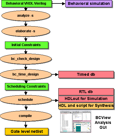

You provide a Verilog or VHDL behavioral description of the desired function, such as a complex multiplier or FFT chip. The main difference between behavioral Verilog/VHDL code and implementation-specific (RTL) code is that the behavioral code can, and should, describe only the function and not be tied to any particular architecture or technology. After you perform the steps through the schedule stage that implements details such as technology and architecture, the trade-offs of circuit throughput versus chip size versus clock period come into play. When you resolve those issues, you can compile the design into cycle-accurate HDL and create a cycle-accurate database for simulation or a gate-level netlist. Then you can simulate at the behavioral, RTL, and gate levels to ensure the final implementation functions as intended. The illustration below depicts these tradeoffs.

In the following Behavioral Compiler session each step from behavioral code to synthesis to RTL code is briefly discussed as you perform the steps of the synthesis. Expanded explanations and alternatives are provided later in this tutorial.
unix% cd bc_tutorial/synthesis
unix% bc_shell | tee Log/synthesis.log
The UNIX tee command after the pipe ( | ) sends screen output (the stream of bc_shell commands) to a log file in the Log directory in addition to the screen. Another way to isolate errors is to pipe the output to the UNIX grep -i error command. The -i switch on grep makes it case insensitive so the output includes Error, errors, or other variations of spelling or case of the error message. For this first session we will watch the entire operation in detail. Notice that the prompt is now bc_shell > which indicates you can now enter Behavioral Compiler and Design Compiler commands.
bc_shell > bc_enable_analysis_info = true
This command, like all dc_shell and bc_shell commands, returns a 1 if the result is successful,and returns 0 if there is an error. Analyze performs a syntax check of your design.
The elaborate command, using the -schedule switch, builds your design from the Verilog module and stores it as a Synopsys database in tool memory for subsequent steps. At this point it would be worthwhile to save your elaborated database.
bc_shell > write -hier -out ./DB/comp_mult_elab.db
The write command saves the design along with the setups, commands you have
executed so far, and commands you have executed through scripts. If you need to
leave the session, you can invoke bc_shell later and read in
the database in to resume from where you stopped by using the following
command:
bc_shell > read ./DB/comp_mult_elab.db
Your design is still in memory, so you do not need to execute the read command to continue this tutorial.
bc_shell > create_clock clk -period 15
bc_shell > bc_check_design -io_mode cycle_fixed
bc_shell > bc_time_design
Because elaboration and timing can take a while, save your design at this point. That allows you to go to the next step, schedule, without having to do elaboration and timing if you want to explore different latency and area tradeoffs or different architectures. To save the design enter:
bc_shell > write -hier -out ./DB/comp_mult_timed.db
After the file is saved, you can exit bc_shell without losing any of your work. Later, you can enter bc_shell and execute a read comp_mult_timed.db command to bring the database into memory for scheduling.
bc_shell > schedule -io_mode cycle_fixed
After scheduling is complete, save the scheduled design.
bc_shell > write -hier -out ./DB/comp_mult_sched.db
Your design is now at the RTL level. If you wanted to simulate this design, you could also write the database out in Verilog or VHDL format. You should also levelize the design so the simulator does not have to traverse the design hierarchy. This makes simulation run faster. For Verilog the commands are:
bc_shell > verilogout_levelize = true
bc_shell > write -hier -f verilog -out ./Verilog/comp_mult_sched.v
For VHDL the commands are:
bc_shell > vhdlout_levelize = true
bc_shell > write -hier -f vhdl -out ./VHDL/comp_mult_sched.vhd
As previously mentioned, you can exit the tool then invoke bc_shell, at a later time and use the read comp_mult_sched.db , command to proceed. The flow illustration shows that you would usually compile the design at this point. In the interest of time, rather than using the compile command, we will use BCView to analyze the scheduled design.
Start BCView with the following command:
bc_shell > bc_view
BCView invokes with 4 or 5 windows. BCView displays 1) HDL Browser window, 2) Selection Inspector window, 3) Finite State Machine (FSM) Viewer, and 4) Reservation Table window. If there are errors, a 5th window displays, the Scheduling Error Analyzer (SEA) window.
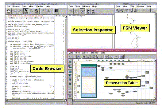
BCView allows you to step through the operation of your design in a cross- highlighted graphical way. When you click on an item in one BCView window, the relevant items are highlighted in the other BCView windows. For example, if you click on a path in the Finite State Machine (FSM) Viewer, the relevant code section in the HDL Browser window highlights and the registers, clocks, I/O ports, etc involved with that state transition are highlighted in the Reservation Table window.
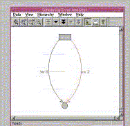
The Scheduling Error Analyzer (SEA) window displays only if there are scheduling errors. It displays a beginning node in the FSM (shown at the top), an ending node in the FSM (shown at the bottom), and the path (transition) between these nodes that Behavioral Compiler was not able to schedule. The right-hand arc is annotated with the constraint that Behavioral Compiler was not able to schedule. SEA also shows another path as a left-hand side arc annotated with the minimum constraint value schedule you need to provide for this path in the FSM to schedule.
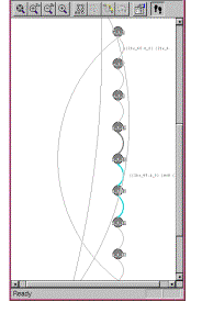
The Finite State Machine (FSM) Viewer derives its display from your behavioral source code after your design is scheduled. States in the state machine are shown as bubbles, and transitions from one state to another are shown as arcs. If you click the left mouse button on a state, the code of that state is highlighted. You can then press the Tab key to execute the transition to the next state. If there is an alternate transition possible out of a state, pressing Ctrl-Tab takes the alternate path.
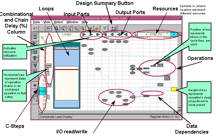
The Reservation Table Viewer displays a lot of information in a very compact format. In the Reservation Table, you can observe whenever I/O ports are accessed, when operations span more than one clock cycle (multicycle operations), what resources (adders, multipliers, etc) are used and when in the design, how loops actually operate, the function of combinational and chain delayed operations, and the position within a clock cycle where an operation occurs. Details of these operations are covered in the Behavioral Compiler class. A full exploration and explanation of these capabilities is beyond the scope of this tutorial, but you can experiment with the cross-highlighting and observe how you can use the FSM Viewer and the Reservation Table to single- step through your design.
When you are done, exit from the bc_shell.
Congratulations! You completed the Synthesis section of this tutorial. A few of the capabilities of Behavioral Compiler were explored and are covered with greater depth in the Behavioral Compiler class.
On to Chapter 3 - Coding for Synthesis with Verilog